

Abstract
This project describes how a robotic finger can be created that can be controlled in any direction. This finger utilizes a 3 air-chamber design as demonstrated in previous research [1], [2]. As each chamber is infalted it causes a bending motion opposite of the chamber location. This actuator contains 3 different air chambers and will be wrapped in a material. This material keeps the actuator from expanding as it is inflated and will force the actuator to bend. The actuator’s goal is to be able to extend as well as bend/curl along any direction. This is possible as different amounts of pressure in each chamber cause the the actuator to bend in different directions and amounts
This actuator will fall into the fiber-reinforced-actuator group, as the entire structure will be wrapped in an inextricable layer. There will be three controllable chambers and varying the pressure in each of them relative to the others should allow for curling motion in any direction relative to its nominal direction.
The purpose of this project is to determine the abilities of actuators and their difficulty of manufacturing. The future goal is that multiple of these actuators could be combined to form a versatile gripper for robotic applications.
Design
I opted to design the entire actuator out of a single piece of silicon. This meant that this was insanely tricky to mold as there were many internal angles and I do not have access to a 3D printer with dissolvable filament. I designed a 4 step mold process in which the core of the actuator is molded and then the edges are molded around that.
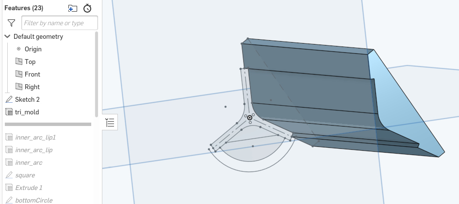
I used Onshape for the first time and things went fairly smoothly. Here you can see part of the mold used to make the inner tri-core: Onshape document is accessible here
Key dimensions of actuator:
- All walls are 2mm thick
- Overall dimaeter of actuator is ~20mm (arbitrarily deciced to ease demolding)
- Length was set to 75mm (arbitraily chosen as long enough to allow for flexing and small enough to print and minimize waste)
Notable design considerations:
- 3d print molds instead of using cardboard
- Mold in multiple steps as opposed to a single step so thatdon’t have to deal with mold extraction problems
- Increased wall thickness and dimensions from reference papers
Fabrication
This yielded a total of 5 3d-printed parts.
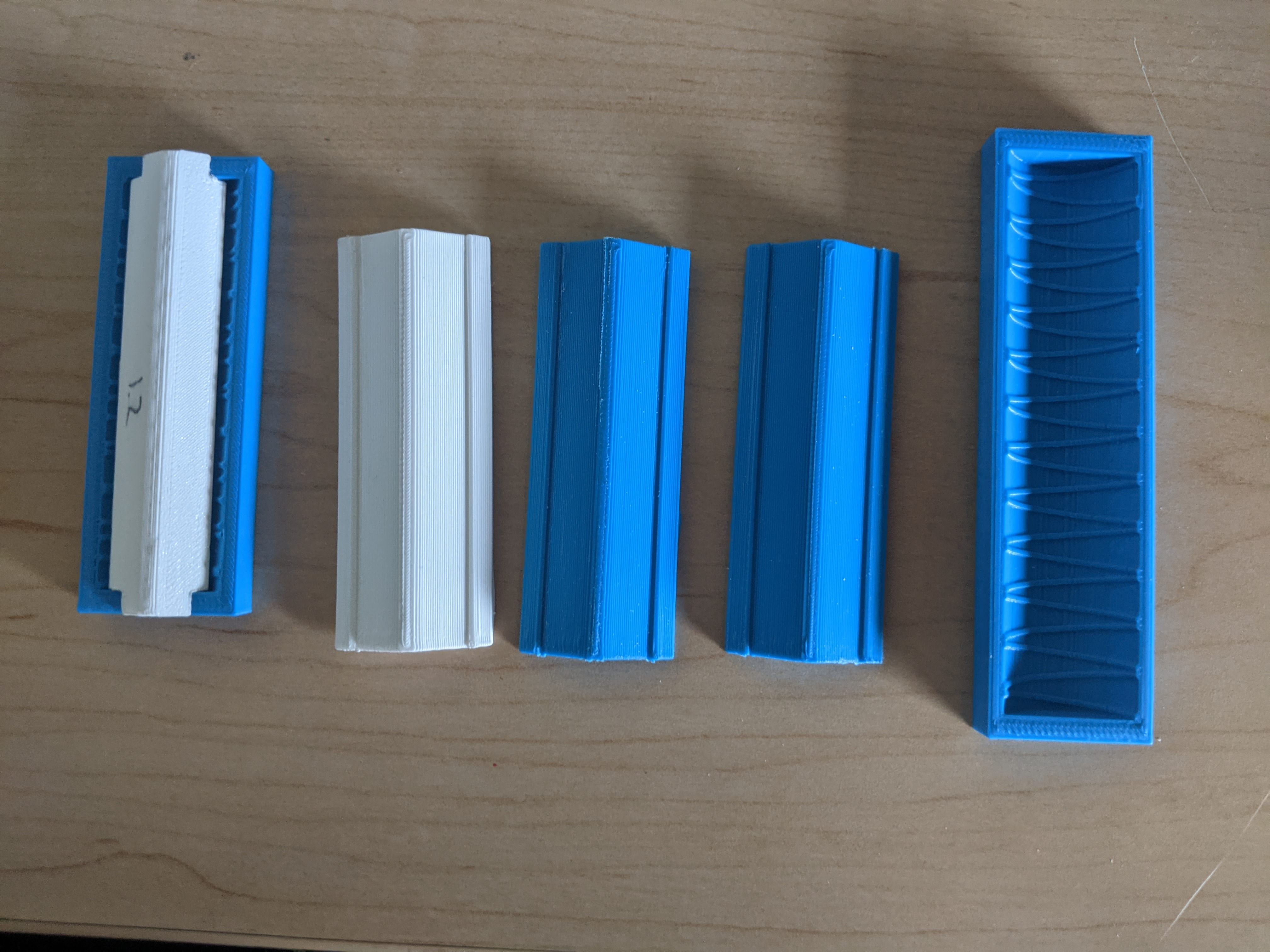
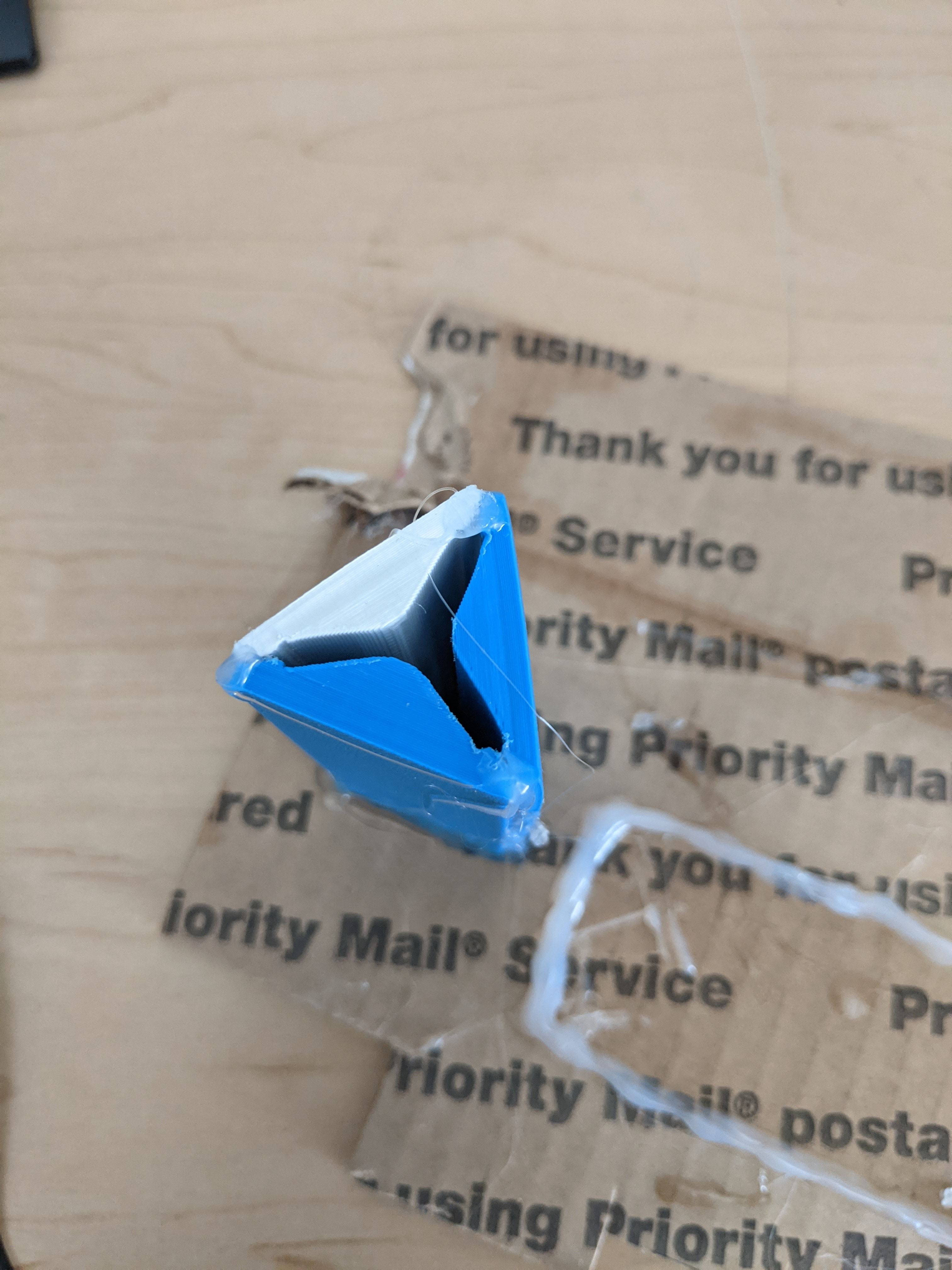
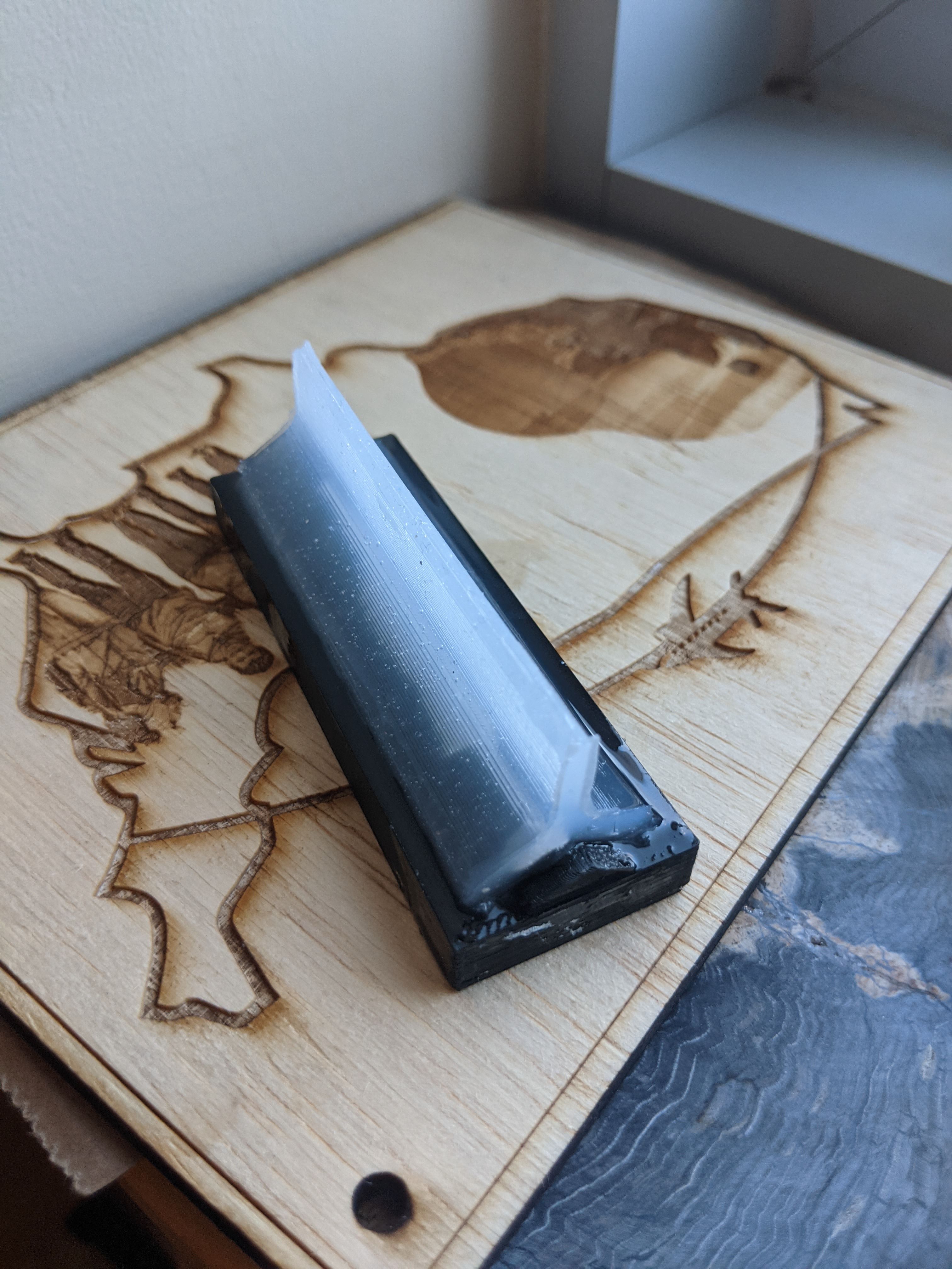
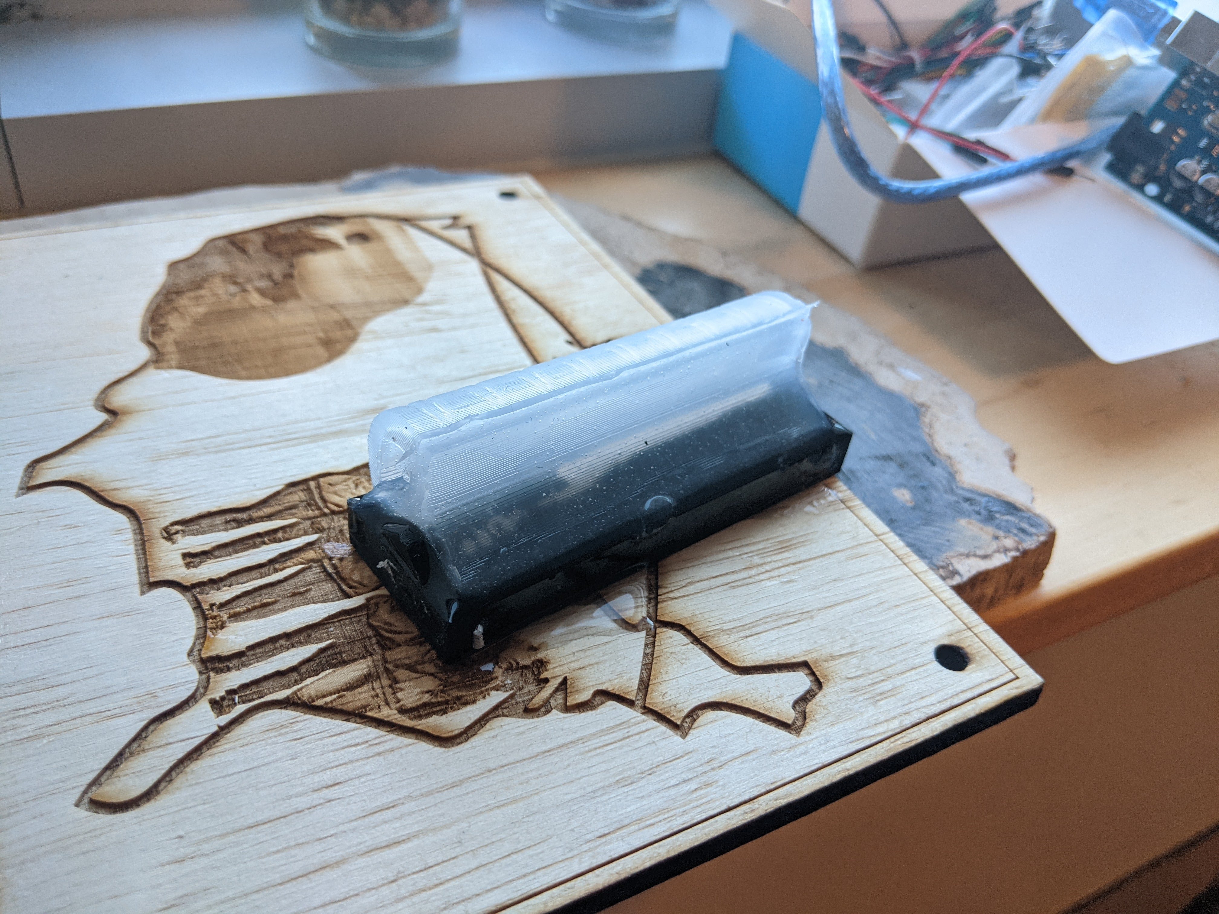
To mold the central triangular column, three of the prints are glued together to form the mold for the central column. These prints can easily be cut apart to aid in demolding.
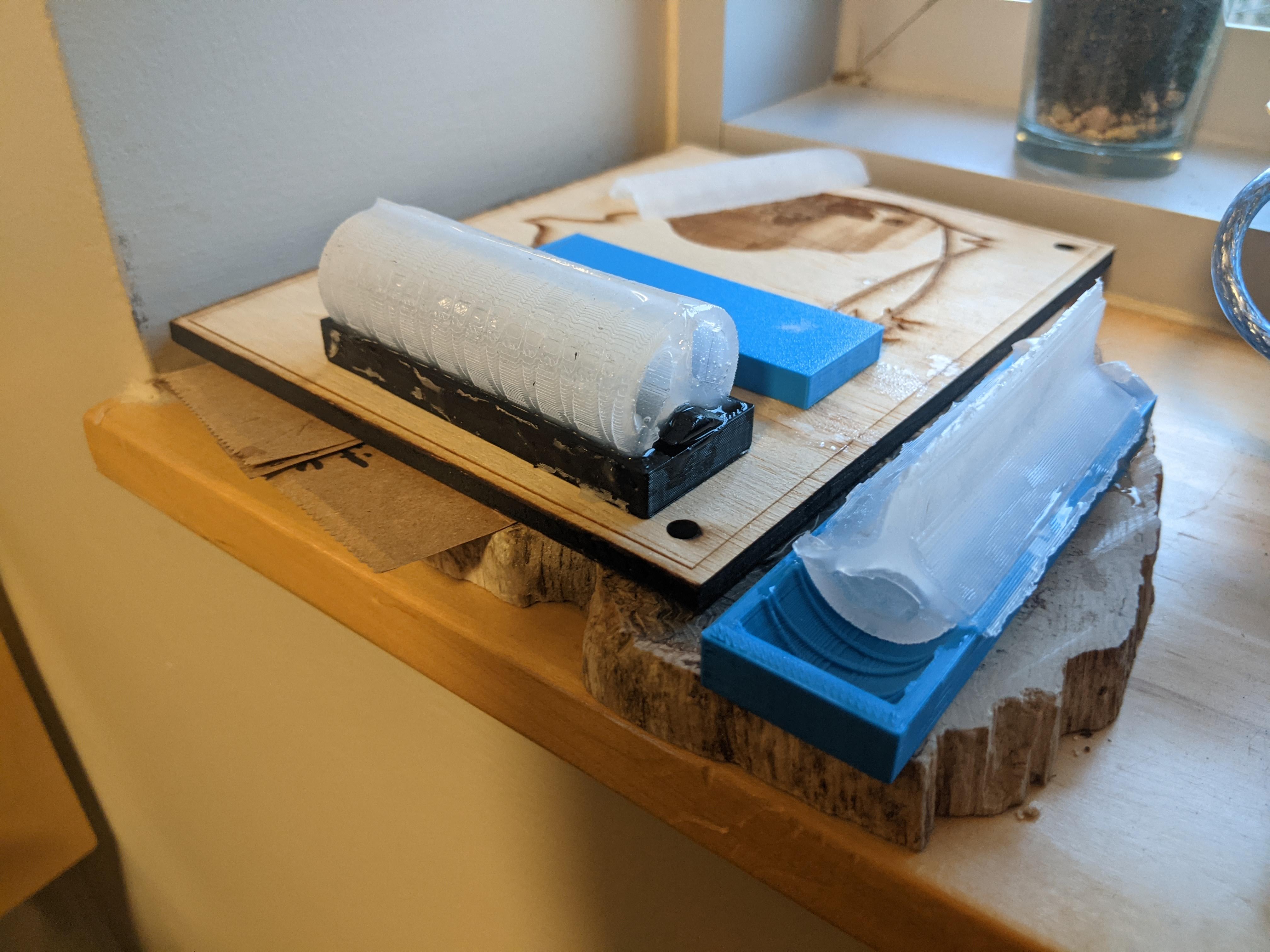
The other parts are used together to hold the core and mold silicon into an arc around it. This is done in 3 seperate molding steps as shown below. This took a long time as it takes >3hrs for the silicon cure
Note:
- I also molded the outer arcs seperately for one actuator and then used silicon to put them together – this also worked fine but it required careful lineup of the silicon pieces
- I didn’t use any mold release/oil it’s likely that I could have done a mold with internal corners etc and used mold release and removed it just fine
Results
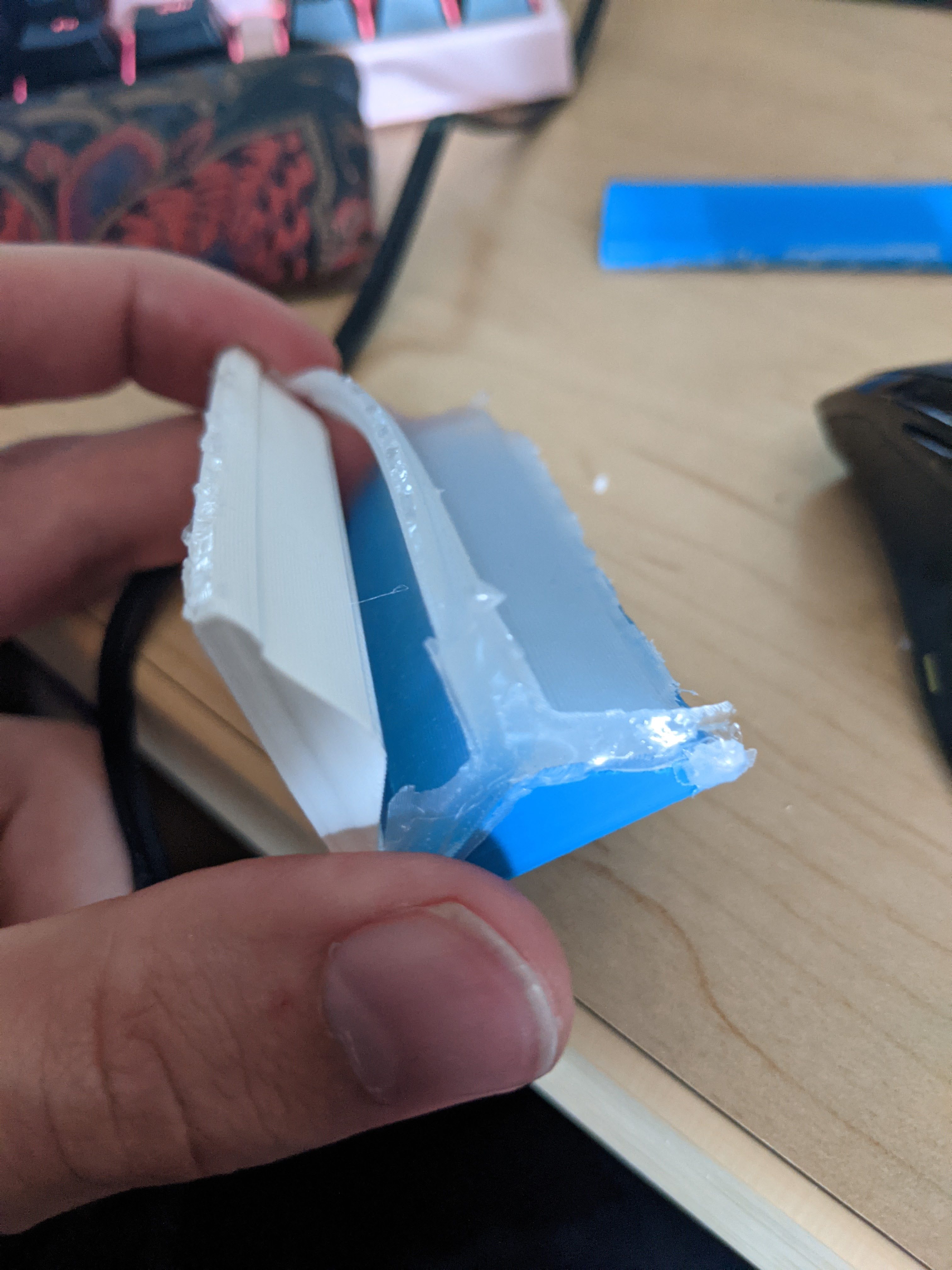
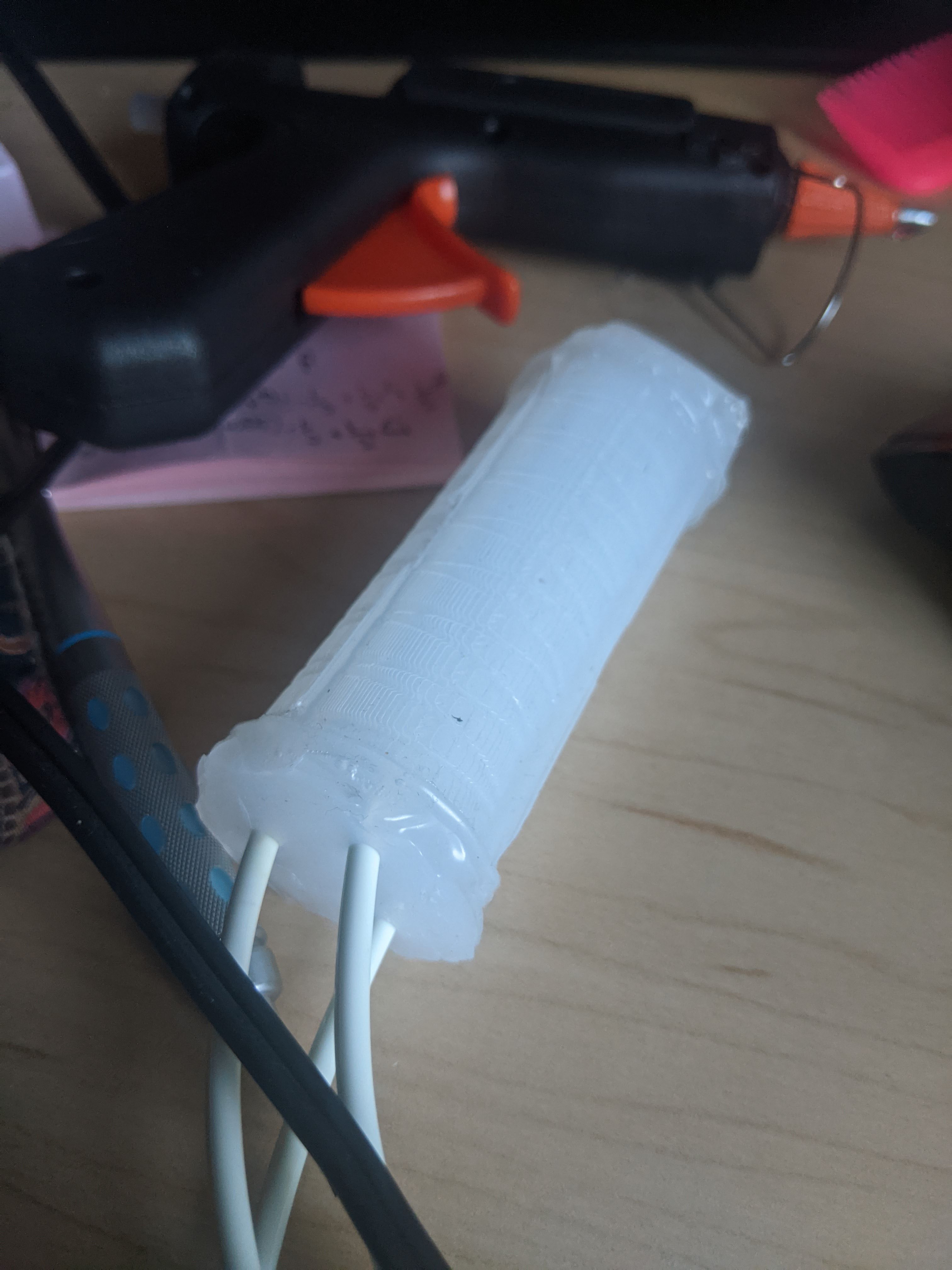
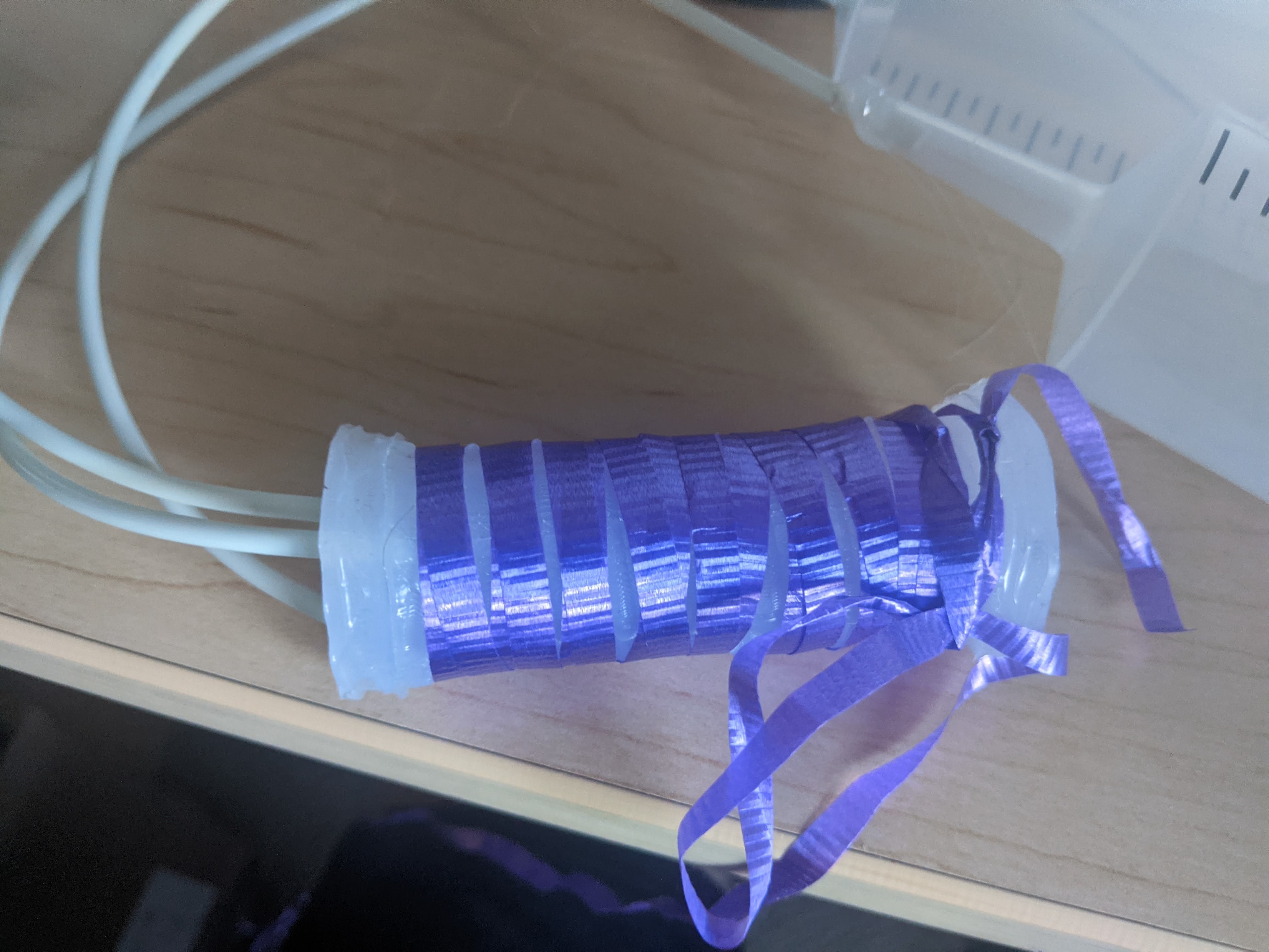
Here you can see the final actuator before and after it was wrapped in ribbon (an inextricable layer that keeps it from simply balooning out):
This actuator works in the ways I anticipated! By controlling the pressure in each chamber, and the ratio of the pressures between chambers the actuator can rotate in a circle and curl in any direction.
I hooked up one syringe to each chamber so that the actuator could move:

It worked as expected and had a large range of motion relative to it’s size(around 2" reach at 90*bend). Below is a gif of it in motion!
Evaluation
I was curious roughly how much pressure my actuator needed to actuate. I managed to find a scale with that could be powered off my arduino (I couldn’t find any AAA batteries). This let me measure the pounds shown on the scale while pushing the syringe down on it. I knew the size of the syringes so I could get a rough “PSI” reading.
Here are some pictures from some of my data collection
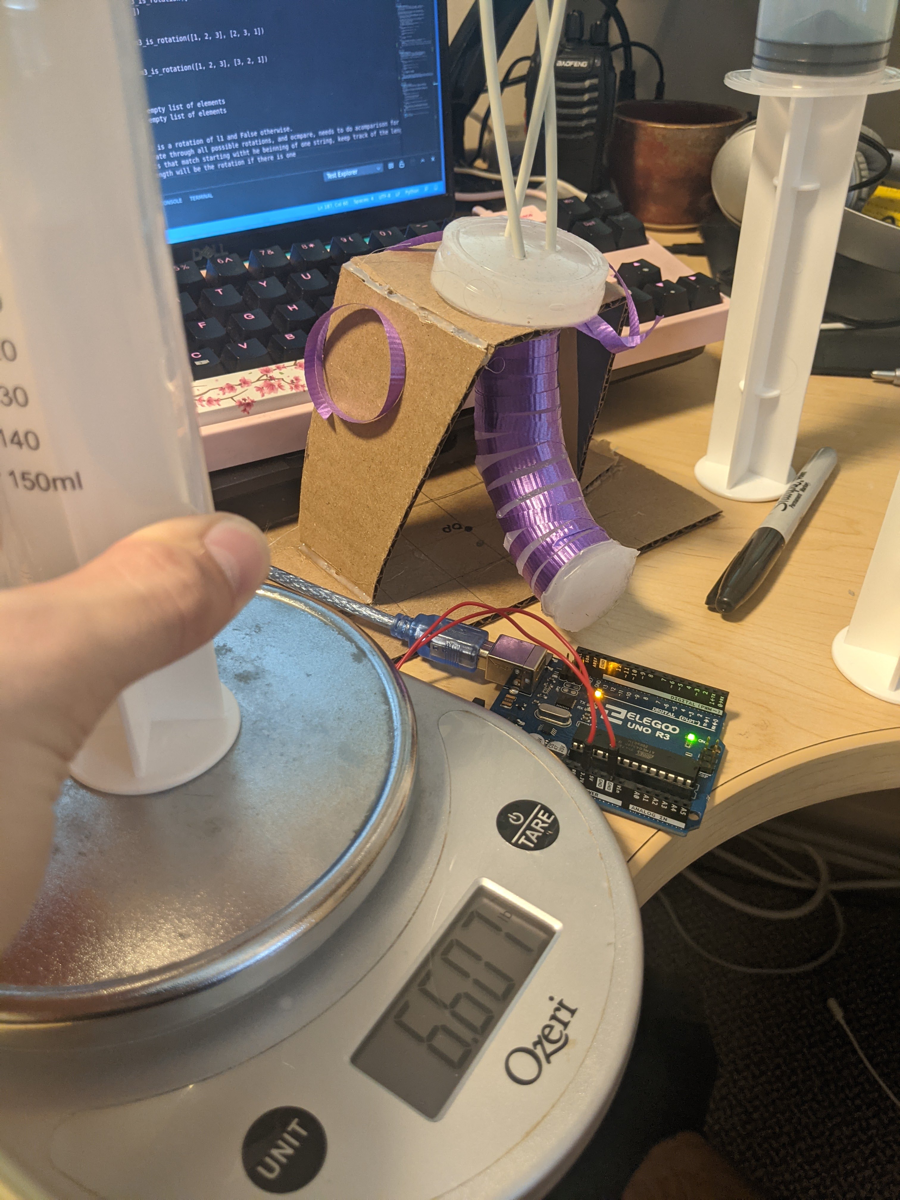
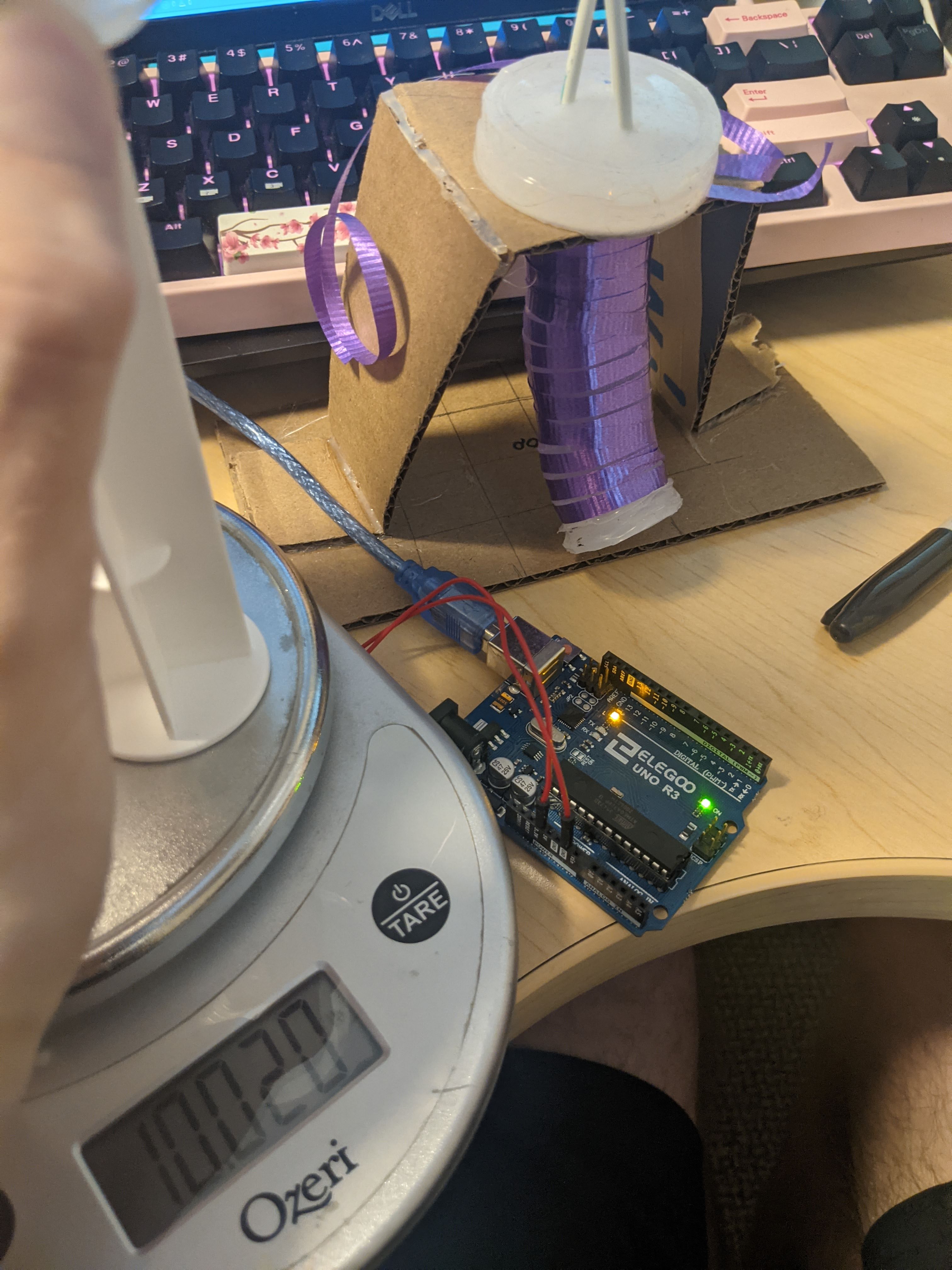
Calculations for 90 bend of actuator* Orange chamber 7.5lbs Blue chamber 5.5lbs Green 6.5lbs to 90*rotation Two chambers at once: 10lbs (less angle)
Area of plunger: .75” radius^2* pi = **1.767”** inches squared
PSI Calculation:
Orange: 4.2psi
Blue: 3.11psi
Green: 3.67psi
Two chambers at the same time: 3psi for each chamber (this had less rotation than the single chambers)
What this means
When converted to kPA, these values are all less than 35 kPa. This is less than the actuation pressure for the previous wrapped actuator and fabric-pneumatic actuator as well as pressures reported for some Pneumnets.
The actuator is easiest to actuate along one of the 3 cardinal directions. This actuator has roughly a 2” reach in every direction. When all chambers are inflated it can extend roughly 25% of its length. I have not pushed the limits on this actuator as I don’t want it to pop – it is likely that higher pressures, bends, and extensions could be achieved.
Reflectiom Lessons Learned
This project managed to mostly fulfill my learning goals. I was really interestd in seeing how something that could be made that lended itself to fine control. I was successful in making an actuator that is a perfect example of such a system. It responds consistently to the same amounts of pressure and has a complex motion (3dof) that requires control for it to be useful. Unforunately I was unable to meet my learning goal of controlling this actuator with an arduino()I didn’t have enough pumps/valves. This is an area that I would like to explore in future projects. I experienced firsthand how time intensive making these actuators was and how it was hardifficult to make two actuators that responded exactly the same to the same inputs/ This was helpful to realize and helps me understand why there are not a wealth of pneumatic/inflating actuators out there.
Other Takeaways:
- Molding is hard and mold complexity shoul dbe minimized (molding and mold design took 90% of my time)
- Circular molds are especially difficult
- 3d printing isn’t always the answer, A cardboard mold could have been made as well and sped up my process
- Single use molds are an option– this could have saved me a lot of time since it was hard to print parts
- Multi-DOF actuators are controllable and give a very complex motion. When multiple actuators are combined, it is likely that very complex behavior could be achieved. Smaller and more of these actuators definitely warrants exploration in the future. As well as a similar design using cable actuation.
Works Cited
[1] K. Suzumori, S. Iikura and H. Tanaka, “Development of flexible microactuator and its applications to robotic mechanisms,” Proceedings. 1991 IEEE International Conference on Robotics and Automation, Sacramento, CA, USA, 1991, pp. 1622-1627 vol.2, doi: 10.1109/ROBOT.1991.131850.
[2] Kawamura, S.; Sudani, M.; Deng, M.; Noge, Y.; Wakimoto, S. Modeling and System Integration for a Thin Pneumatic Rubber 3-DOF Actuator. Actuators 2019, 8, 32. https://doi.org/10.3390/act8020032